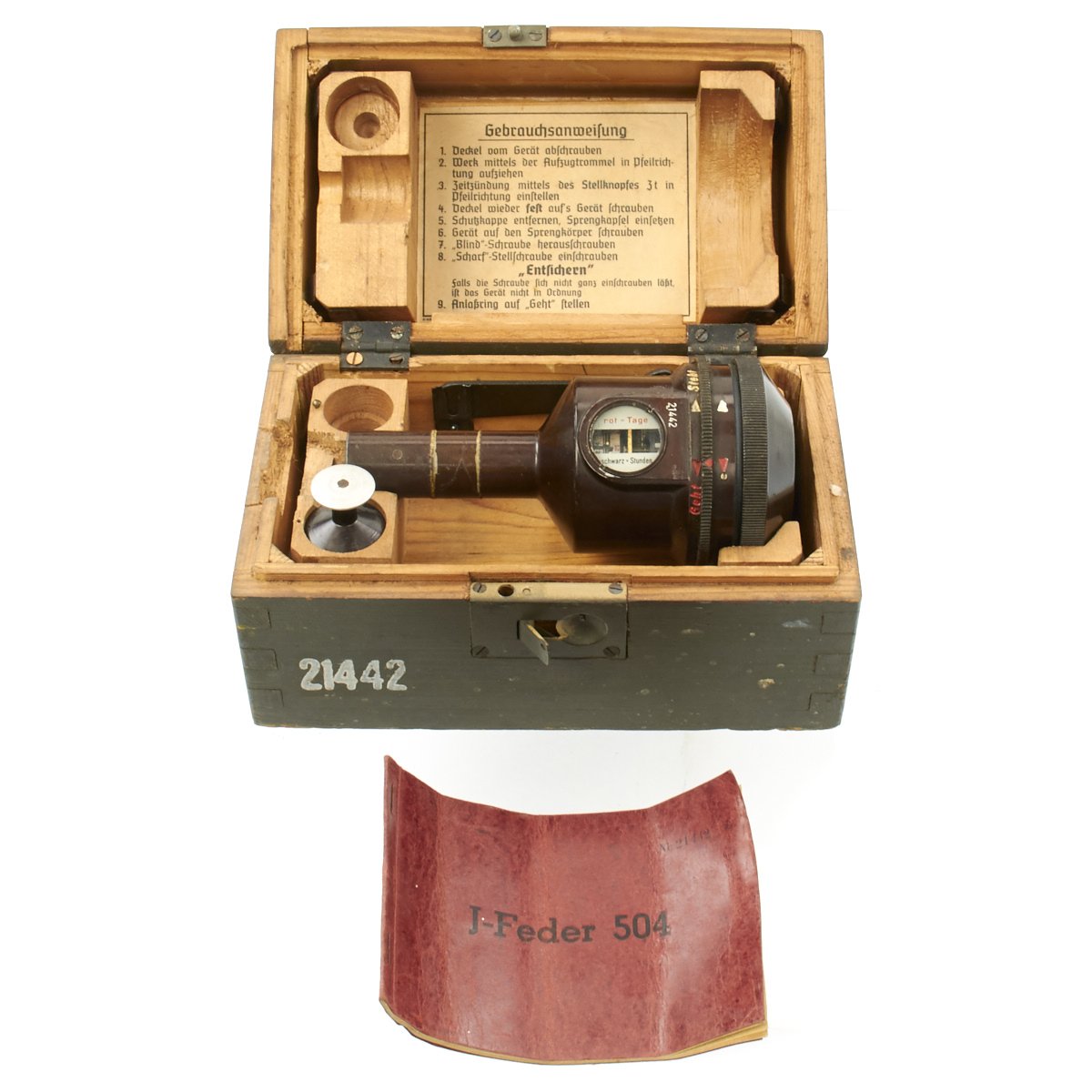
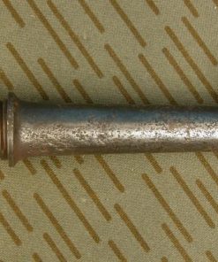
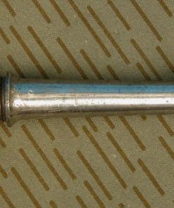
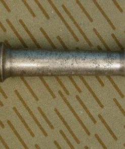
Original German WWII J-Feder 504 Time Delay Fuze in Transit Chest Original Items
$ 495,00 $ 148,50
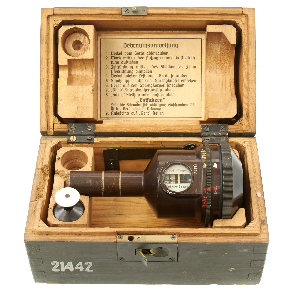
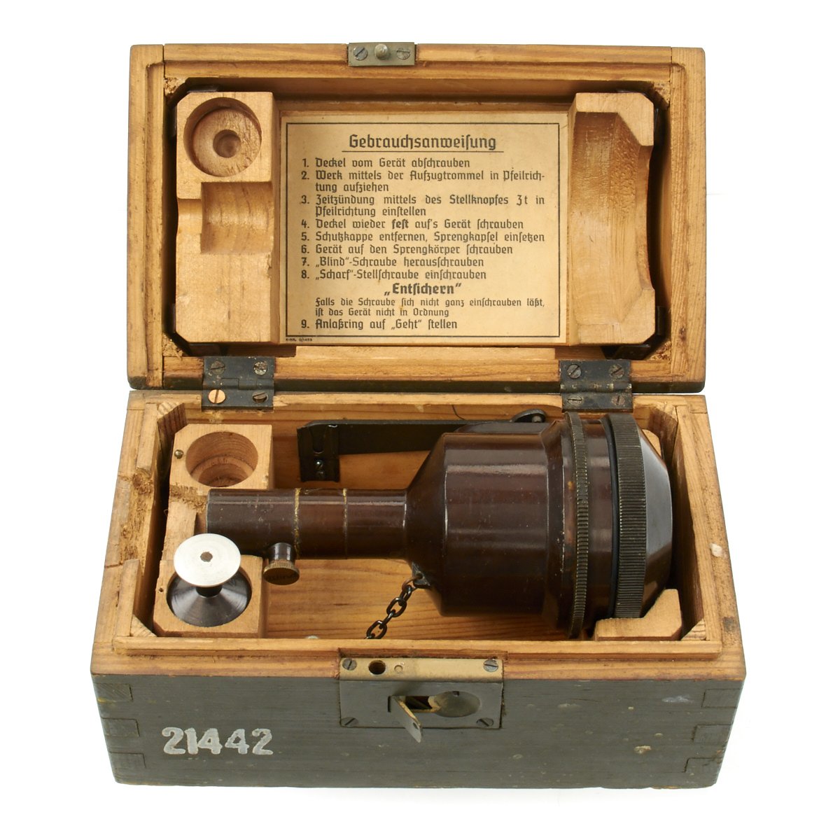
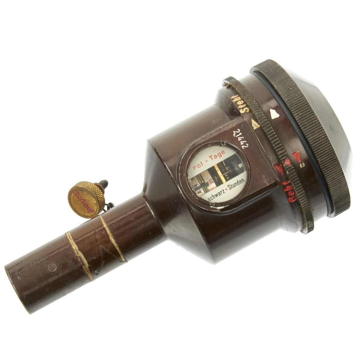
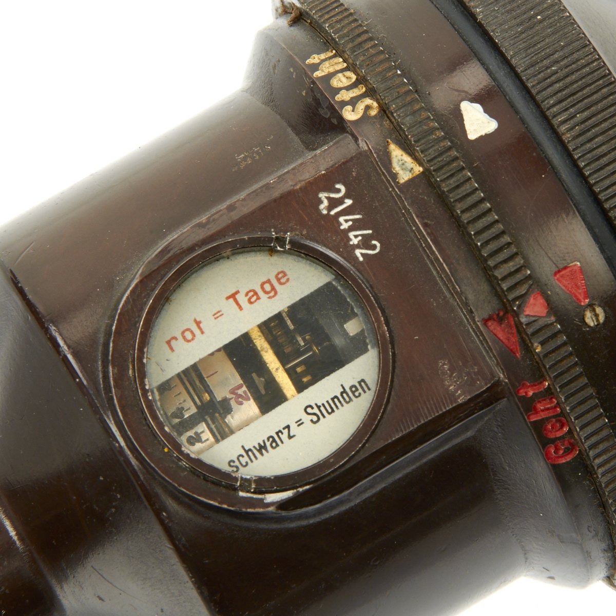
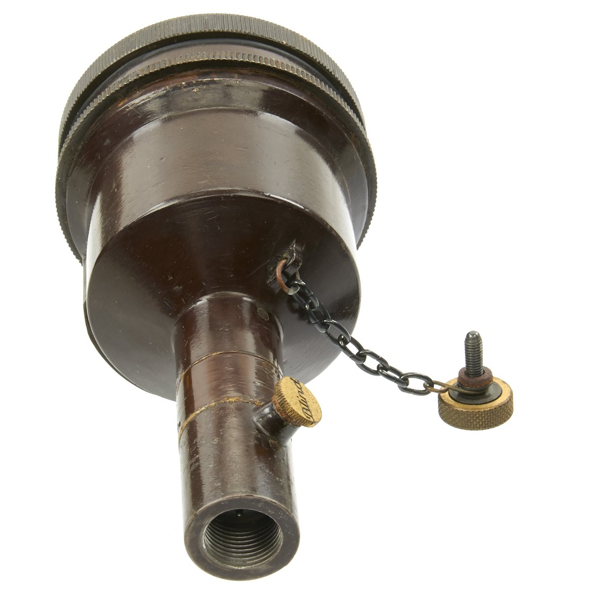
Original item: Only One Avaialble. This is a superb mint condition example of a German WW2 J-Feder 504 Boxed Long Delay Fuze. This is a German World War Two explosive fuse that could be set for detonation anywhere from 15 minutes to 21 days. The fuse could be attached to a large explosive device and used to ambush allied forces advancing through Europe. The fuse’s mechanism, including the red day dial and black hour dial, can be seen through the round viewing window. To the right of the window is the serial number 21422 with a waffenamt. The same serial number can also be seen under the screw on cap. The arming screw and chain are present w/ the screw being marked in red “Scharf”.
Original wooden box in field green paint stenciled J-FEDER 504 and 21442. Box contains additional parts along with paper instruction label mounted to the internal in the lid. Also included is a red book marked J-Feder 504. Inside the book are German stamps with a dated of January 28, 1945.
Overall condition of all parts is excellent.
The body is an aluminum casting which in its upper portion houses the clock, and in its lower portion the striker mechanism. The top is closed by a screwed cap with a rubber ring washer below it and into the base is screwed the cap holder having leather washers.
On removing the cover the clock is exposed. The knurled cylinder is provided for winding the clock while the center knob is for setting the clock for any desired delay up to 21 days. The minimum delay is 15 minutes (1/4 hour). The delay times are marked on the edges of the disks; the days are in red, and the hours are in black. The setting is visible through the window and is indicated by the pin. This latter is connected with the lever arm which allows the trip lever to release the striker at the end of the delay period. At the 24-hour marking on the black-inscribed disk and at the 21-day marking on the red-inscribed disk are slots which allow the pin to move into the channel. These slots are aligned at the zero reading at which position the striker is released. The slot in the disk is covered by a lightly-sprung steel strip which is pushed back by the pin as the clock approaches the zero setting. At this strip can only be pushed in one direction, it provides a safety device to prevent the striker being released while the clock is being set by the knob.
A further safety device for the preservation of the clock mechanism is provided by the bend steel wire. This passes through, and is secured to the spindle, so that when the latter rotates with the lever at the end of the delay period the short limb of this steel wire presses against the balance wheel and stops the clock. If this was not provided the clock could continue working and further rotation of the disks, the pin would jam or would be deformed. This is important since provision is made for testing the clock and its though that the clock mechanism may be intended for re-use.
The clock is started by the movement of the ring through an angle of about 30°. Two screws, passing through the ring, project into the clock mechanism. Between them is the lever arm to which is attached a thin spring steel strip. In the stop (steht) position this latter is in contact with the balance wheel of the clock and holds it. When the red mark on the ring is moved to the go (geht) position the lever moves the steel strip so that it gives motion to the balance wheel and then moves clear of it. The ring is held by either the “stop” or “go” positions by the shaped steel spring, ad the lever arm is held by the shaped spring. The striker mechanism is retained in the body by the four screws. The striker is held in the cocked position by the trip lever. The movable piece is a transport safety device. In the “safe” position this is pushed over by the spring strip so that the striker is prevented from reaching the cap. The screw marked “scharf” replaces this when the apparatus is set for action. The stem of this screw projects far enough into the striker mechanism to push over the movable safety piece to allow the full movement of the striker when released. The accessory is provided with the equipment. It screws in, in place of the cap holder, ad is to be used for recocking the striker after test or after use. At the end of the delay period, the lever arm on the rotating control disk bears against the trip lever, causing it to release the striker. The striker, driven by the striker spring, is then forced into the percussion cap, firing it.
Fast Shipping with Professional Packaging
Thanks to our longstanding association with UPS FedEx DHL, and other major international carriers, we are able to provide a range of shipping options. Our warehouse staff is expertly trained and will wrap your products according to our exact and precise specifications. Prior to shipping, your goods will be thoroughly examined and securely secured. We ship to thousands clients each day across multiple countries. This shows how we're dedicated to be the largest retailer on the internet. Warehouses and distribution centres can be located throughout Europe as well as the USA.
Note: Orders with more than one item will be assigned a processing date depending on the item.
Before shipping before shipping, we'll conduct a thorough inspection of the items you have ordered. Today, the majority of orders will be delivered within 48 hours. The delivery time will be between 3-7 days.
Returns
The stock is dynamic and we cannot completely manage it because multiple stakeholders are involved, including our factory and warehouse. So the actual stock may alter at any time. It's possible that you may not receive your order once the order has been made.
Our policy is valid for a period of 30 days. If you don't receive the product within 30 days, we are not able to issue a refund or an exchange.
You can only return an item if it is unused and in the same state as the day you received it. You must have the item in its original packaging.
Related products
Uncategorized
Band of Brothers ORIGINAL GERMAN WWII Le. F.H. 18 10.5cm ARTILLERY PIECE Original Items
Uncategorized
Uncategorized
Uncategorized
Uncategorized
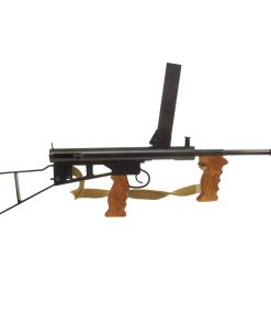
Australian WWII Owen MK1 Machine Carbine SMG Custom Fabricated Replica with Sling Original Items
Uncategorized
Uncategorized
Uncategorized
Uncategorized
Uncategorized
Uncategorized
Uncategorized
Armored Burgonet Helmet & Polearm from Scottish Castle Leith Hall Circa 1700 Original Items
Uncategorized
Uncategorized
Uncategorized
Uncategorized
Uncategorized
Uncategorized
